Monday, February 17, 2014

Test Equipment: Clone Saleae Logic Analyzer


A fellow ham recently pointed out this very inexpensive Logic Analyzer  ($10 CDN) from seller mhestore2009 on eBay, and I had to get one. It is a much less expensive clone of the real Saleae Logic Analyzer. I thought that writing this short review might be interesting to others.


If this vendor does not have it any more, there are lots of others that do.
 
It came complete with a USB cable and some connector cables, you download the software from here.
 
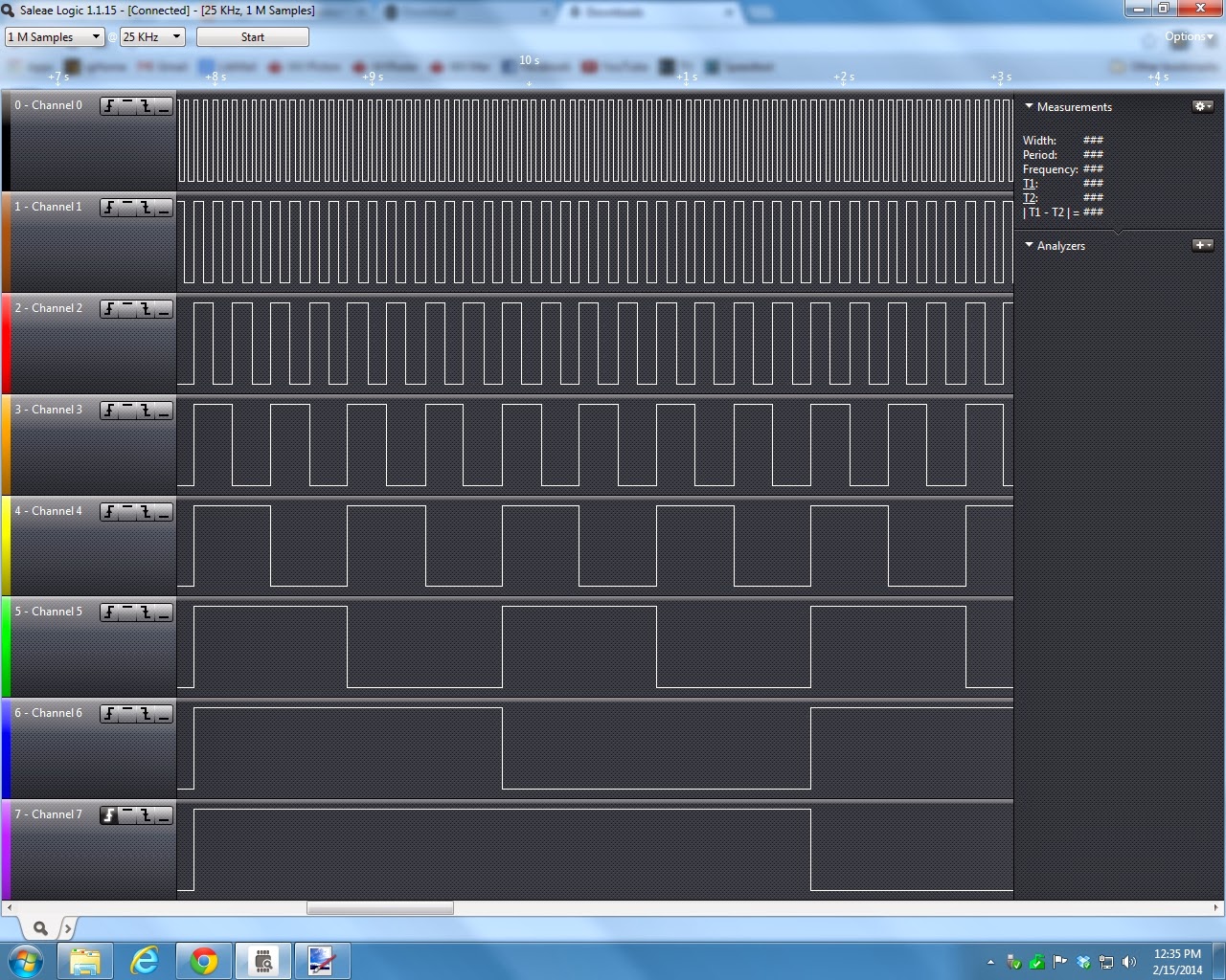
It was dead easy to set up, and the software is very easy to use. Here is a screenshot of the display of an 8 bit binary counter (coming out of a PICAXE, actually), click on it for a larger version:
 
 
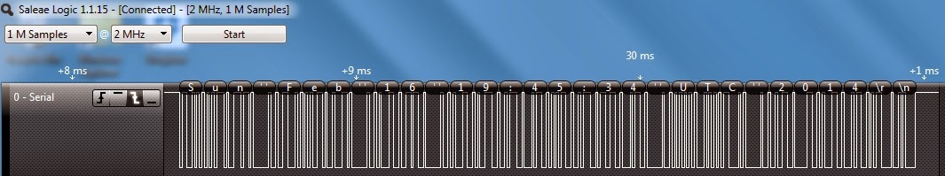
Next is a display of a serial communications stream from a Raspberry Pi and a dumb terminal (it seemed to pick up the 0 to 3.3 volt logic OK). Note that the software actually understands the ascii serial protocol and displays the characters transmitted along with the logic levels:


Lastly, here is the display of an I2C stream between a Raspberry Pi and a PICAXE chip:


As well as Serial and I2C, the software can decode and display SPI, CAN, 1-Wire, UNI/O, I2S/PCM, MP Mode 9-bit Serial (i.e. Multidrop and Multiprocessor mod), Manchester, DMX-512, Parallel, JTAG*, LIN*, Atmel SWI*, MDIO*, BiSS C*, PS/2 Keyboard/Mouse*, HDLC*, HDMI CEC*, and USB 1.1*.  (* currently in beta).
 
I have kind of mixed feelings about these Chinese clones using software that has been developed for more expensive hardware. It will be interesting to see how the real Saleae Logic Analyzer company reacts, maybe they will add a serial code or some other test to the software to block the clones from using it.
 
On the other hand, I think that makers and hobbyists are the main target for the clones, and maybe the company will allow the clones to use their software, assuming that real companies with critical projects will by the real thing from them. Will have to see how it plays out.
 
 
Eric Pierce VA3EP - See the Disclaimer in the Introduction

© Eric Pierce and "VA3EP Amateur Radio And Other Geek Pursuits", 1952-2099. Unauthorized use and/or duplication of this material without express and written permission from this blog’s author and/or owner is strictly prohibited. Excerpts and links may be used, provided that full and clear credit is given to Eric Pierce and "VA3EP Amateur Radio And Other Geek Pursuits", with appropriate and specific direction to the original content.


Sunday, February 9, 2014

Test Equipment: Oscilloscope for less $30 CDN


When at the PICAXE site recently, I saw this really interesting and inexpensive assembled Oscilloscope board. Right after a Digital Multimeter, an Oscilloscope is the most desired piece of test gear for working on electronics. This one is very inexpensive and affordable and although limited to audio and slower digital frequencies, is still good for basic use, so I thought this review might be useful to others. Quoting directly:
     "Many people who enjoy electronics as a hobby or in education (where budgets are always tight) don't always need a super-high-end oscilloscope but instead rather require something that is very affordable yet highly usable in practice.
     The PCB-scope is just that - simple to use, yet with a full feature set as you will find on professional instruments. The Windows software is free of charge and the PCB-scope connects via a standard micro-USB cable (as used by most cameras, mobile phones and e-readers, not included).
     PCB-scope grew out of the earlier DPScope project to see how a PCB based scope design could be simplified yet still give the functionality, look and feel of a real oscilloscope."

All of the required documentation (including schematics) and free software (which does most of the heavy lifting) are available for download. I purchased one from a local supplier, ABRA in Montreal. This is what the bare board looks like:


The headers are not already soldered in when you get it, depending on your application, you can solder the single sided one on the top for connections, or the double sided one for plugging into a proto board.

If you read my previous articles on breadboards here and here, you know that I like to have things mechanically robust, so I decided to mount mine scope board inside a project box with external connectors to protect it from harm. So using basic hand tools, I cut holes in a small project box for the board in the bottom, access for the USB cable on the side, 3 BNC connectors (for analog channel 1 and 2 and trigger - most real 'scopes use BNC connectores) and a 4 port RCA female connector for the logic probe signals on the top.


Then I wired things up, using wire wrap wire and my manual wire wrap tool to connect from the top header (I did not solder the bottom header on) to the connectors on the front where the wires are soldered on. I used some heat shrink tubing to keep the connections to the BNC connectors from shorting out (the BNC connectors are from my junk box, and are PCB mount types).  The RCA connectors are also from my junk box, from a scraped DVD player.


Once the box was closed up (after testing) I added some labels using a ???? label maker.


Here is a screen shot of the PC software (most of the heavy lifting is done by your PC)  displaying a 1Khz sine wave from my ancient HP 204B sine wave signal generator on both channels. Yes, there is a bit of distortion on the top of the sine wave (which is coming from the generator, I confirmed that on my HP 1740A Analog 'Scope):


Believe it or not, this inexpensive Oscilloscope has the ability to display the frequency spectrum of the signal as well using Fast Fourier Transforms in the software. 


You will notice that there are large even harmonics at 2, 4, etc. KHz, and smaller odd harmonics as well. You will also notice that there are no calibrations for the scales on either screen (this is the way real 'scopes are). However, if you tick off the "cursors" box movable cursor lines will read off the values on the vertical scale, no matter if calibrated in volts or dB and on the horizontal scale. Also, on the Utilities menu there is a selection called "Measurement" which displays just about every parameter of what is shown on the screen.

The software also supports a Digital Voltmeter function as well as dual channel data logging to a file and 4 channel digital logic analyzer function.

One operational issue, I found that you should connect the device before starting the software, AND stop the software before disconnecting the device. I found that not doing it in that order resulted in it not finding the device on occasion.

All in all, pretty amazing for a $30 board.


Eric Pierce VA3EP - See the Disclaimer in the Introduction

© Eric Pierce and "VA3EP Amateur Radio And Other Geek Pursuits", 1952-2099. Unauthorized use and/or duplication of this material without express and written permission from this blog’s author and/or owner is strictly prohibited. Excerpts and links may be used, provided that full and clear credit is given to Eric Pierce and "VA3EP Amateur Radio And Other Geek Pursuits", with appropriate and specific direction to the original content.

Saturday, February 1, 2014

Presentation: Raspberry Pi at the OLA Conference


I did a presentation on the Raspberry Pi at the Ontario Library Association Conference on Friday (as part of my "day job").


Here is the description from the presentation:

"ENGAGE ELECTRONIC MAKERS WITH A RASPBERRY PI WORKSHOP
Eric Pie
rce, IT Co-ordinator, County of Prince Edward PL & Archives

Since its release in 2012, millions of Raspberry Pi $35 credit-card-sized single-board computers have sold. Used by electronic makers of all ages to build projects such as media players, home automation and security, Internet-connected dog treat dispensers, and more. Learn how to present a hands-on workshop demonstrating the basics to engage a cross section of library patrons."


A lot of libraries (and schools) are doing MakerSpaces to engage patrons, and there were a number of presentations on this theme at the conference.


Eric Pierce VA3EP - See the Disclaimer in the Introduction

© Eric Pierce and "VA3EP Amateur Radio And Other Geek Pursuits", 1952-2099. Unauthorized use and/or duplication of this material without express and written permission from this blog’s author and/or owner is strictly prohibited. Excerpts and links may be used, provided that full and clear credit is given to Eric Pierce and "VA3EP Amateur Radio And Other Geek Pursuits", with appropriate and specific direction to the original content.